
European
Southern Observatory
New Technology Telescope
New Technology Telescope

|
|
European
Southern Observatory
New Technology Telescope |
|
| General : |
 |
 |
 |
 |
 |
| Observations : |
 |
 |
 |
 |
 |

2.1 Setup of the instrument
2.1.1 MOS plate mounting
2.1.2 Punching head mounting
2.1.3 Offsets adjustment
2.2 Plate punching
2.2.1 The MOS User Interface
2.2.2 Operational procedure
2.3 Check the punching
2.4 Trouble shooting
2.5 Summary of operations
2.5.1 Setup
2.5.2 Plate punching
Use EMMI configuration panel.
To put the desired location of the starplate wheel on the load point, do the following:
PLEASE BE SURE THAT YOU INSTALL A THIN PLATE IN THE STARPLATE WHEEL,
OTHERWISE YOU MIGHT BREAK THE PUNCHEAD
Physically mount a virgin MOS plate on the position located at the load point. Then update the configuration doing the following:
Check the display on the right part of the GUI to check that the configuration is correct.
NOTE: it is important to declare that position 1 is punchable. This
is the default but you can double check on the right part of the GUI.
Use EMMI configuration panel.
Install the requested punching head inside EMMI. Then update the configuration:
Also, as the size of the punch head is a parameter for the MIDAS context emos, the following file on wg5ops should updated:
/midas/[Midas version]/contrib/emos/dat/emominslit.dat
example: in july 1997, the Midas version used is 96NOV
/Midas/96NOV/contrib/emos/dat/emominslit.dat
This file contains the width and the heigth in microns of the punch head. Those data are given in paragraph 1.3 as a function of punching head number.
IMPORTANT: At that point, execute emiBackup command to save your configuration
(this command can be executed directly from the emouifConfig panel as an option
in the File pull-down menu).
2.1.3 Offsets adjustment
Once the MOS plates have been loaded and the requested punching head mounted, the setup procedure consist in adjusting the punching offsets. Those offsets are set so that the punches performed on the plate are done exactly at the place where they were requested.
As an example, these offsets have been adjusted on July 01st, 1997 when using
punching head #7 and we got:
offset_X (enc) = -1488
offset_Y (enc) = -361
IMPORTANT: As you have punched a plate to perform the setup, always
remember to replace it with a new one and update the EMMI configuration panel.
From EMMI OS GUI under the tools menu, select the MOS
option. This action will "pop-up" the MOS GUI.
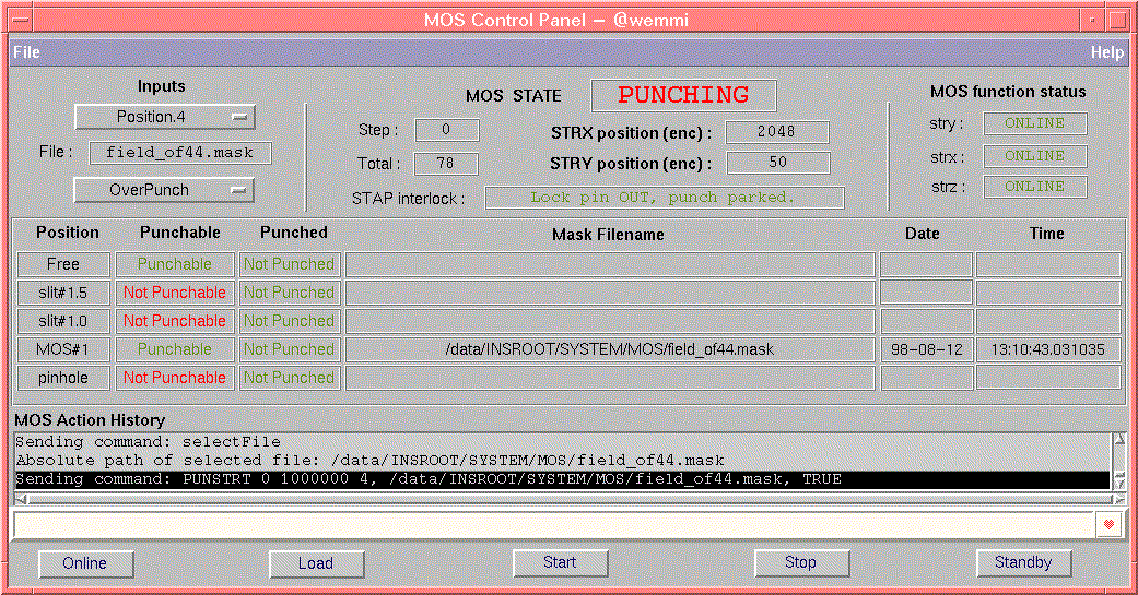
[Click the image to enlarge]
| Widget Element | Description |
|---|---|
| Position | To select wheel position were plate to be punched will be loaded (Only positions 2 to 5 are available for holding plates. Position 1 is always free) |
| File | Name of file containing the coordinates of position where to punch. |
| Overpunch/No_overpunch | To enable or disable the possibility to punch a plate already punched |
| Step | This element tells how many slits have already been punched |
| Total | This shows how many slit positions will be punched |
| STRX position | encoder position of STRX EMMI function |
| STRY position | encoder position of STRY EMMI function |
| Position | starplate position |
| Punchable | show if this position is available for punching or not |
| Punched | show if this position was already punched |
| Mask Filename | shows name of file containing the data of positions used to punch this particular plate |
| Date | Date when this plate was punched |
| Time | Time when this plate was punched |
| Online | to set MOS functions to online. Initializes & enables STAP STRX STRY STRZ & STRL functions |
| Load | Load file with position data. Name of this file was given in File element |
| Start | Start the punching procedure |
| Stop | Stop punching (punching cannot be restarted again) |
Put the module ONLINE by pressing the "Online" button at the lower part of the MOS GUI. Wait for the initialization of all units (the state of strx stry strz units should change to ONLINE).
Enter the name of the file containing the position of the slits to be punched
by pressing the "Load"
button. This files should be in the following directory:
/vltdata/tmp/EMOS-MASKS
The files will have an extension ".mask"
On the MOS GUI select the position that will be punched. In case that the plate is already punched and new slits need to be added, select the "over-punch"option.
Start the punching procedure by pressing the "Start" button.
The punching procedure has the following steps:
In case you want to interrupt the punching process before it finishes, press
"Stop" button.
Once all slits have been punched, and if no other plate has to be punched
quit the MOS module. The state of strx stry strz units will remain
ONLINE, but if the mask has been punched correctly to the end, this will not
cause problems. If you wish to have them in "Standby" anyway the only
way to do so is to re-initialize EMMI.
2.3 Check the punching
The plate that has been punched should be examined to make sure that all the
slits have been done.
This cannot be made directly as once punched, the MOS plate cannot be removed
from the starplate wheel (the alignment would be lost as warned in section 1.4).
Therefore the check has to be done by taking an exposure with an internal calibration
lamp. This can be done either with a suitable calibration template if you have
one available or simply directly on the EMMI OS panel.
On the adapter B GUI:
On the calibration lamp GUI
On EMMI OS GUI:
The image you get should contain all the slits previously defined. For an
easier check, check the image on /data/raw/YYYY-MM_DD on wg5off to display it
within xm and overlay the mask that served to define
the punches (you'll have to ftp it from wlmos) or simply compare with a
finding chart you have printed when you finished the mask drawing.
2.4 Trouble shooting
The troubles you might run into can be divided into 2 classes; the one that have never been reported before and the ones that are olf rriends of us (altough we are chasing them). A list is given here of those known problems and a suggested workaround.
Here are the steps to be followed when one is performing a setup:

| Send comments to: Emanuela Pompei & Paul Le Saux
<epompei@eso.org>, <plesaux@eso.org> Last Update: Mar. 17, 2004 (GM/EC) |
     |